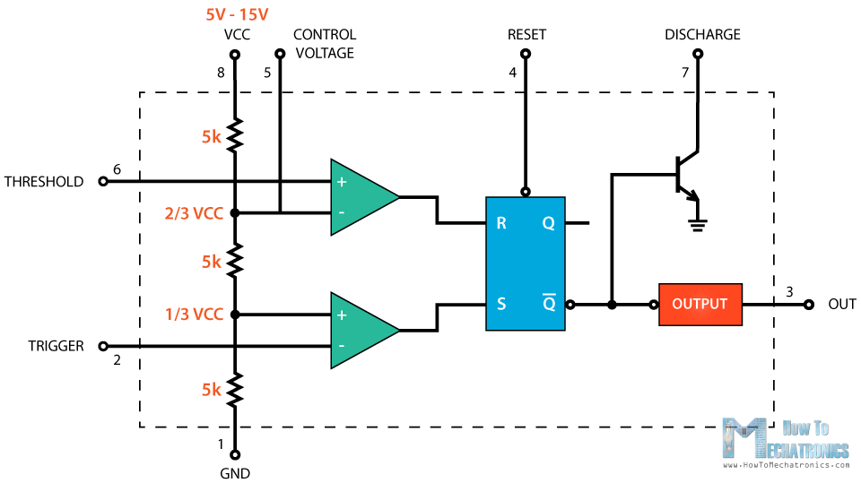
Time of high pulse output can be manually reset by pulsing the reset pin to low. When trigger and threshold, both comparators are outputting a high signal, the flip flop switches output to low output. When the trigger comparator outputs a low signal (whatever the output of threshold comparator), the flip flop switches to high output. The two comparators outputs are the inputs of a flip-flop.

It is a circuit that can be in one of two states based on the state of inputs. The comparator 2 connected to pin 6 compares the threshold input to a reference voltage of 2/3 of Vcc. The comparator 1 connected to pin 2 compares the trigger input to a reference voltage of 1/3 of Vcc. A threshold is a non-inverting input to the comparator 2. Trigger is the inverting input to the comparator 1. Many transistors are used for this comparator purpose. It is a circuit that compares an input with a reference voltage (whether an input is a higher or lower voltage than a reference) and outputs a low or high signal. This picture shows the pinout diagram of the timer IC. All these modes are discussed in later sections.

Most importantly, it has three different modes of operation namely astable, monostable and bistable mode. It has a simple circuit design, easy to use and cost-effective due to which it is used in a wide variety of applications. 555 is a timer oscillator IC introduced by an American company named Signetics and is intended for use in timing applications for generating long time delays, pulse generation, and frequency division.


 0 kommentar(er)
